
Instructions for NodeMCU
What do I need?
- 1 NodeMCU-compatible board with ESP8266 (e.g. NodeMCU 1.0 devkit)
- 1 MPU6050 accelerometer
- 3 LED (red, yellow, blue)
- 3 resistors (100~180 Ohm)
- Some “dupont jumper” cables
- 1 breadboard
A shopping list?
Here it is! Attention: some sellers offer multiple items in packages, but quantities needed are those indicated above
How to assemble everything?
This is the wiring:
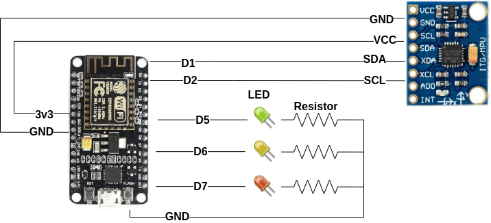
Steps are:
- Place the NodeMCU on top of the breadboard straddling the two zones (the breadboard has two “zones”, separated by a groove)
- Place the MPU6050 sensor in an area of the breadboard so that its pins are on different lines than those occupied by the NodeMCU pins
- Position the three LEDs on three different lines (which are not already used by the NodeMCU or MPU6050 sensor), across the breadboard deck. Remember that in the LEDs the shortest pin is the negative (and therefore must be put, as in the diagram, towards
GND) while the longest pin towards the positive (i.e.D5,D6orD7depending on the color. - Insert the three resistors (no matter the direction) with a pin on the same row and same area of the negative of the LEDs (one for each LED), and with the other on the same row of one of the
GNDpins of the NodeMCU - Insert the dupont cables to connect
D5,D6andD7to the respective colored LEDs in the area and in the row of the breadboard corresponding to the longest pin of the LED in question (e.g. a dupont cable betweenD5and the row with the positive pin of the green LED) - Insert the dupont cables to connect
VCC,GND,SDAandSCLof the MPU6050 to pins3V3,GND,D1andD2of the NodeMCU respectively
The software
Now you need to load the software: follow the instructions according to your platform!
 Windows
- Download the tool “NodeMCU Flasher”: 64 bit version or 32 bit version.
- Download the NodeMCU driver from this link, decompress the ZIP and launch the installer
- Download the sensor firmware from this link
- Plug your NodeMCU in your PC
- Open the software “NodeMCU flasher” and choose the NodeMCU serial port
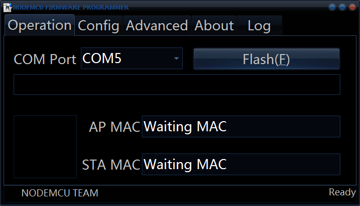
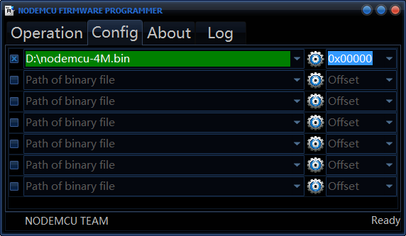
- Open the “Config” tab and choose the firmware file that you just downloaded
- Go back to the “Operation” tab and press “Flash”. At the end of the procedure you can unplug your device and place it wherever you want!
- Once powered on, the device will create a WiFi network named “SeismoCloud”. Join this WiFi network, a configuration panel will appear where you can configure the WiFi settings for your WiFi network (e.g. add SSID and password). Once saved, the device will reboot and it will connect to the WiFi.
- Connect the mobile phone to the same WiFi network as the sensor, open the SeismoCloud app and press the button with the “+” symbol: the app will find the new sensor and allow you to configure its position and name :-)
Done!